- High Q-Factors / Low insertion loss
- High power handling
- Excellent temperature stability
- Best return loss
- High stop-band rejection
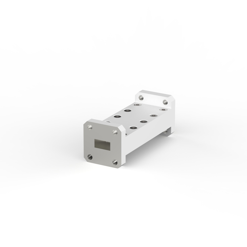
C-Band Transmit Reject Filter (P/N: 222.23003)
Frequency Range
Return Loss
Insertion Loss
Isolation
Waveguide Interface
Dimensions
3.40 to 4.20 GHz
20 dB min.2
0.15 dB max.2
40 dB min.2 (within 5.725 to 6.725 GHz)
CPR-229F with 5.1mm through holes (WR229/R40)
130 x 98.6 x 69.8 mm

X-Band Receive Reject Filter (P/N: 213.23006)
Frequency Range
Return Loss
Insertion Loss
Isolation
Power Handling
Waveguide Interface
Dimensions
7.90 to 8.40 GHz
20 dB min.2
0.35 dB max.2
65 dB min.2 (within 7.25 to 7.75 GHz)
2’000 W max.2
CPR-112F with M4 threads (WR112/R84)
189 x 90.5 x 44.5 mm

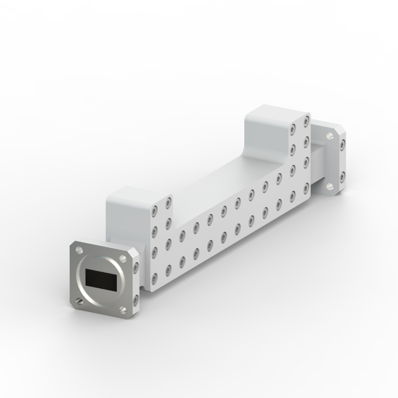
X-Band Transmit Reject Filter (P/N: 213.23007)
Frequency Range
Return Loss
Insertion Loss
Isolation
Waveguide Interface
Dimensions
7.25 to 7.75 GHz
20 dB min.2
0.35 dB max.2
90 dB min.2 (within 7.90 to 8.40 GHz)
CPR-112G with 4.2mm through holes (WR112/R84)
290 x 76.5 x 44.5 mm

Ku-Band Receive Reject Filter (P/N: 213.24030)
Frequency Range
Return Loss
Insertion Loss
Isolation
Power Handling
Waveguide Interface
Dimensions
13.00 to 14.80 GHz
20 dB min.2
0.45 dB max.2
60 dB min.2 (within 10.70 to 12.75 GHz)
2’000 W max.2
PBR-120 with 4.2mm through holes (WR75/R120)
225 x 54 x 38.1 mm
Ku-Band Receive Reject Filter (P/N: 213.24033)
Frequency Range
Return Loss
Insertion Loss
Isolation
Power Handling
Waveguide Interface
Dimensions
12.75 to 14.80 GHz
20 dB min.2
0.45 dB max.2
60 dB min.2 (within 10.70 to 12.50 GHz)
2’000 W max.2
PBR-120 / UBR-120 with 4.2mm through holes (WR75/R120)
225 x 56.3 x 38.1 mm
Ku-Band Transmit Reject Filter (P/N: 213.24032)
Frequency Range
Return Loss
Insertion Loss
Isolation
Waveguide Interface
Dimensions
10.70 to 12.50 GHz
20 dB min.2
0.4 dB max.2
60 dB min.2 (within 12.75 to 14.80 GHz)
PBR-120 / UBR-120 with 4.2mm through holes (WR75/R120)
250 x 41.8 x 38.1 mm

Ku-Band Transmit Reject Filter (P/N: 213.24034)
Frequency Range
Return Loss
Insertion Loss
Isolation
Waveguide Interface
Dimensions
10.70 to 12.75 GHz
20 dB min.2
0.4 dB max.2
60 dB min.2 (within 13.00 to 14.80 GHz)
PBR-120 / UBR-120 with 4.2mm through holes (WR75/R120)
250 x 41.1 x 38.1 mm
Ku-Band DBS Transmit Reject Filter (P/N: 222.24004)
Frequency Range
Return Loss
Insertion Loss
Isolation
Waveguide Interface
Dimensions
10.70 to 12.75 GHz
23 dB min.2
0.2 dB max.2
60 dB min.2 (within 17.30 to 18.40 GHz)
UBR-120 with 4.2mm through holes (WR75/R120)
110 x 38.1 x 38.1 mm

DBS-Band Ku-Receive Reject Filter (P/N: 213.25001)
Frequency Range
Return Loss
Insertion Loss
Isolation
Waveguide Interface
Dimensions
17.30 to 18.40 GHz
20 dB min.2
0.15 dB max.2
70 dB min.2 (within 10.70 to 12.75 GHz)
PBR-140 with 4.2mm through holes (WR62/R140)
UBR-140 with M4 threads (WR62/R140)
90 x 33.3 x 33.3 mm

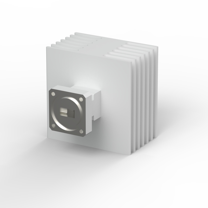
Ka-Band Transmit Bandpass Filter (P/N: 213.26001)
Frequency Range
Return Loss
Insertion Loss
Isolation
Power Handling
Waveguide Interface
Dimensions
28.05 to 30.00 GHz
21 dB min.2
0.4 dB max.2
50 dB min.2 (within 17.30 to 27.10 GHz & 31.00 to 33.00 GHz)
600 W max.2
UG-1530/U grooved (MIL-F-3922/63B) with UNC 4-40 threads (WR34/R260)
70 x 50 x 50 mm
Ka-Band Transmit Bandpass Filter (P/N: 213.26002)
Frequency Range
Return Loss
Insertion Loss
Isolation
Power Handling
Waveguide Interface
Dimensions
28.00 to 29.10 GHz
21 dB min.2
0.4 dB max.2
20 dB min.2 (within 17.30 to 27.10 GHz)
55 dB min.2 (within 30.00 to 33.00 GHz)
500 W max.2
UG-1530/U grooved (MIL-F-3922/63B) with UNC 4-40 threads (WR34/R260)
70 x 50 x 50 mm
Ka-Band Transmit Bandpass Filter (P/N: 213.26003)
Frequency Range
Return Loss
Insertion Loss
Isolation
Power Handling
Waveguide Interface
Dimensions
27.00 to 30.00 GHz
21 dB min.2
0.4 dB max.2
50 dB min.2 (within 17.30 to 26.00 GHz & 31.00 to 33.00 GHz)
600 W max.2
UG-1530/U grooved (MIL-F-3922/63B) with UNC 4-40 threads (WR34/R260)
85 x 50 x 50 mm
Ka-Band Transmit Bandpass Filter (P/N: 213.26004)
Frequency Range
Return Loss
Insertion Loss
Isolation
Power Handling
Waveguide Interface
Dimensions
27.00 to 31.00 GHz
21 dB min.2
0.4 dB max.2
50 dB min.2 (within 17.30 to 26.00 GHz & 31.00 to 33.00 GHz)
600 W max.2
UG-1530/U grooved (MIL-F-3922/63B) with UNC 4-40 threads (WR34/R260)
85 x 50 x 50 mm
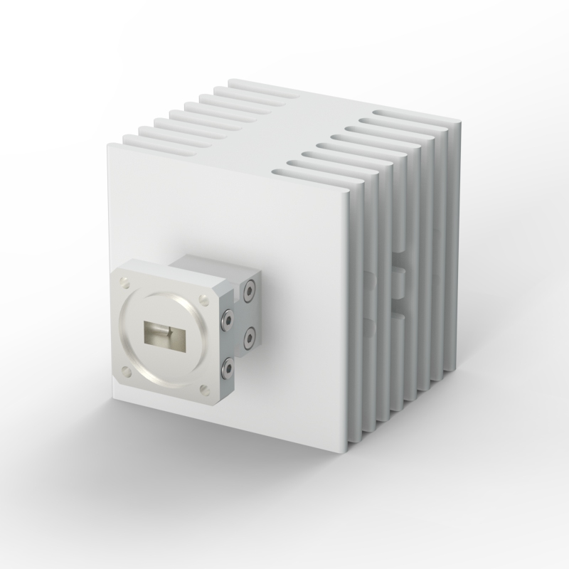
Ka-Band Harmonic Reject Filter (P/N: 222.25001)
Frequency Range
Return Loss
Insertion Loss
Isolation
Power Handling
Waveguide Interface
Dimensions
15.00 to 22.00 GHz
21 dB min.2
0.2 dB max.2
40 dB min.2 (within 34.0 to 60.0 GHz)
200 W max.2
UBR-180 with 4mm through holes (WR34/R260)
80 x 31 x 31 mm
1 typical values: Indication for most-common expectable performance within the specified bandwidth.
– for Returnloss and Port/Port Isolation the statistical mode of total passband is represented.
– for Insertionloss and Axial Ratio the statistical mean of total passband is represented
2 min./max. values: Committed specification value, e.g. worst-case performance within limited ranges of passband with tolerance margins