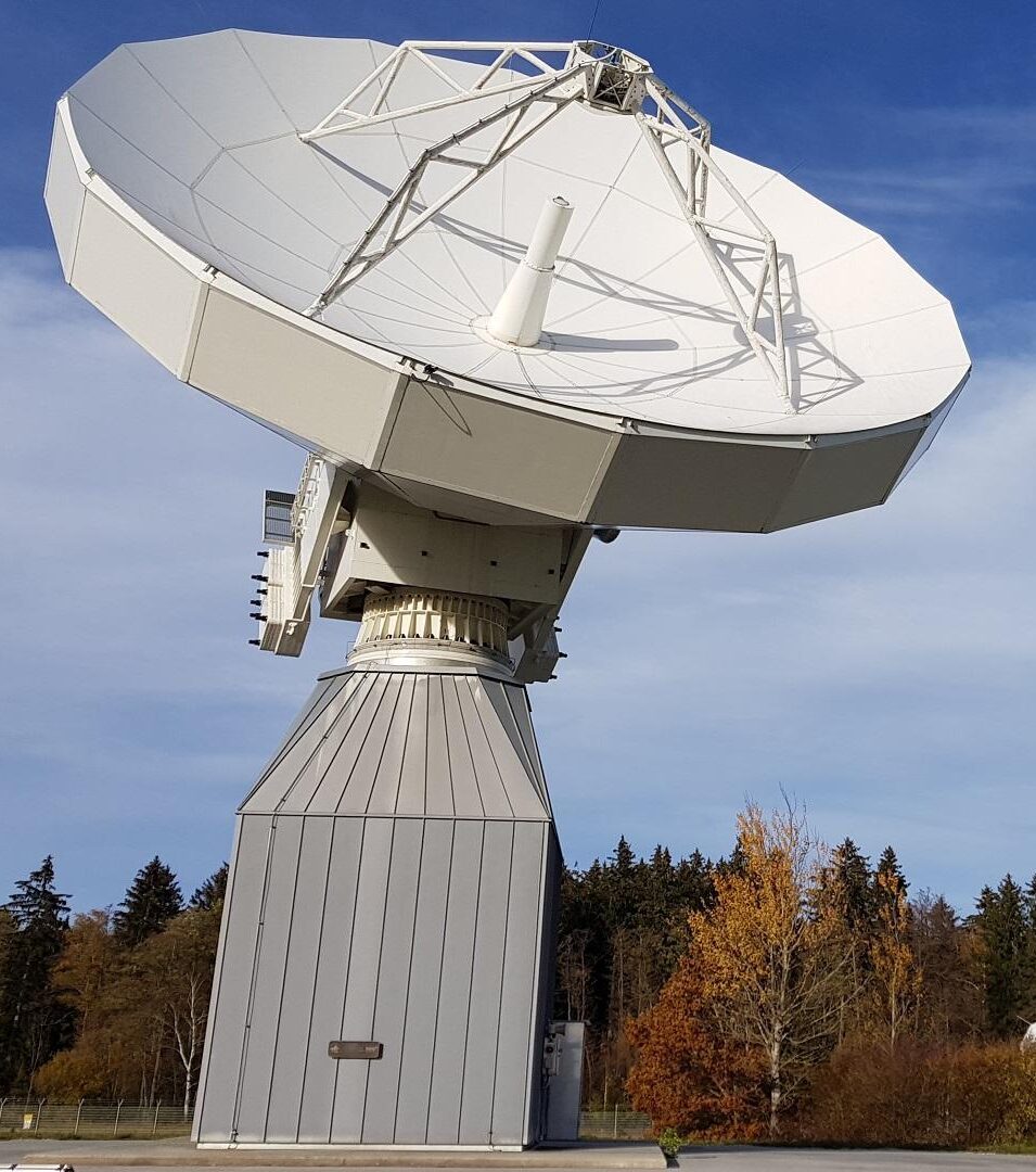
In the early 2000s, more and more satellite missions were planned to collect large amounts of data or to enable broadband communications. At that time, however, only few ground stations for deep space and near-Earth missions were able to provide adequate up- and downlink capacity. Therefore, the needs to use higher frequency bands such as the Ka-band became more and more important. Ka-band offers a link advantage of up to 600% over X-band. Planned Ka-band missions include Earth observation-, lunar-, Mars- and various commercial satellite communications missions.

In this context, a Ka-band antenna was an indispensable component of a modern ground station infrastructure. At that time, several projects and potential missions were envisioned that required Ka-band support in Europe. Another important aspect of Ka-band communications is that frequencies above 10 GHz are strongly affected by weather conditions: rain, snow, clouds, etc. To improve performance and get more benefit from Ka-band frequencies, propagation research must be conducted. Operating a Ka-band antenna enables this research, which includes beacon measurement experiments from Ka-band satellites.
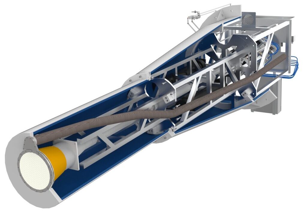
The figures illustrate the feed with and without tube (left), a detailed view (middle) and the installed feed in the center of the main reflector (right)*
For this reason, the German Space Operation Center (GSOC), a division of the German Aerospace Center (DLR), decided to commission the relevant industry in 2009 to develop a K/Ka-band ground station to be operated at its site in Weilheim, Germany. MIRAD microwave was selected as part of the consortium for the development of this complex antenna system and was responsible for the antenna design (reflector shaping) and the development of the corresponding feed system. The main function of the feed system is to switch between two modes of operation, Earth Observation (EO) mode and the second mode for commercial purposes (COM), which means the switching between K- and Ka-band frequncy ranges. Both modes allow simultaneous signal reception and transmission, while both receive bands are equipped with TE21 monopulse couplers to ensure antenna trackability. In addition, each signal path is equipped with a polarization switch to select either circular or linear signal polarization. In linear mode, the feed can be rotated inside the feed tube to adjust the polarization. In addition, the system is equipped with a redundancy network to ensure high reliability in operation. After successfull testing MIRAD delivered the feed system in 2011 to the system integrator. Since summer 2012 the antenna is in operation and still work with excellent performance.
Key technical challenges:
- Combination of two tracking frequency bands
- Complexe polarization switching for all bands
- Feed system polarization adjustment mechanism for linear polarized signals
- Broadband application 18.1 to 31.0 GHz in one system
- Precise antenna reflector design including analysis like G/T, gravitational deformation, sureface tolerances, etc.
- K-band signal transmission EO
(Tx: 22.55 – 23.15 GHz, Rx: 25.5 – 27.0 GHz) - Ka-band signal transmission COM
(Rx: 18.1 – 21.2 GHz, Tx: 27.5 – 31.0 GHz) - Dual circular/ linear polarisation (switchable)
- Polarization adjustment
- Tracking capability in both bands
- Switching between operation modes (EO/COM)


