The first payloads launched in 2016 and 2019 for the European Data Relay System (EDRS) system are the Sentinel-1 and -2 satellites of the Copernicus Program also known under Global Monitoring for Environment and Security (GMES). The EDRS consists out of a constellation of GEO satellites that transmit information and data between satellites, spacecraft and ground stations. EDRS will provide data relay services to the Sentinel satellites and enable high-speed downlink for large quantities of visual material that require high data rate transmission.
EDRS infrastructure consists of two geostationary payloads, a ground system consisting of a satellite control centre, a mission and operations centre, a feeder link ground station (FLGS), and data ground stations (DGS). The European Space Agency (ESA) funded the ground segment infrastructure and and commissioned the industry to built four ground station antennas, two in Weilheim (Germany), one in Redu (Belgium) and one Harwell (United Kingdom). In this infrastrucutral project MIRAD microwave has been requested to design and deliver antenna feed systems for all three (RDGS, HDGS, FLGS, BFLGS) ground segment antennas in 2013. A fifth additional feed system has been ordered and delivered in 2018 to our customer.
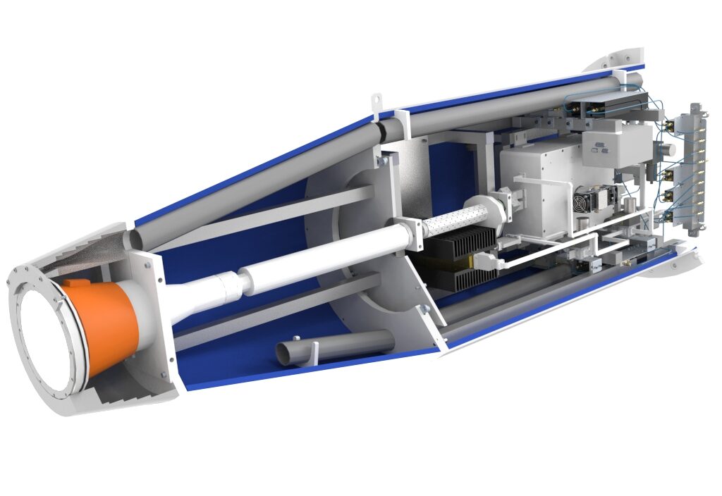
Due to the fact that each ground segment location had different requirements for testing and operational conditions, three different and very complexe feed systems including redundancy switching Rx & Tx networks have been built. The feed systems are used for In-Orbit Testing (IOT), Telemetry (TM), Data Downlink (RX DL), Telecommand (TC) and Tracking (Trk) operations.
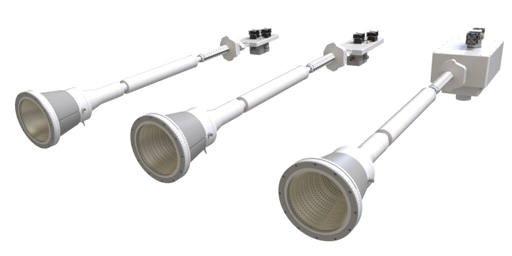
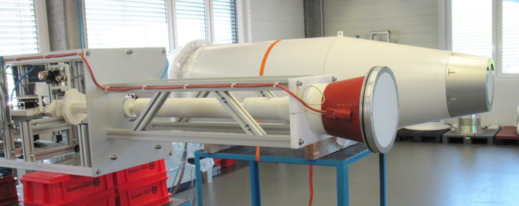
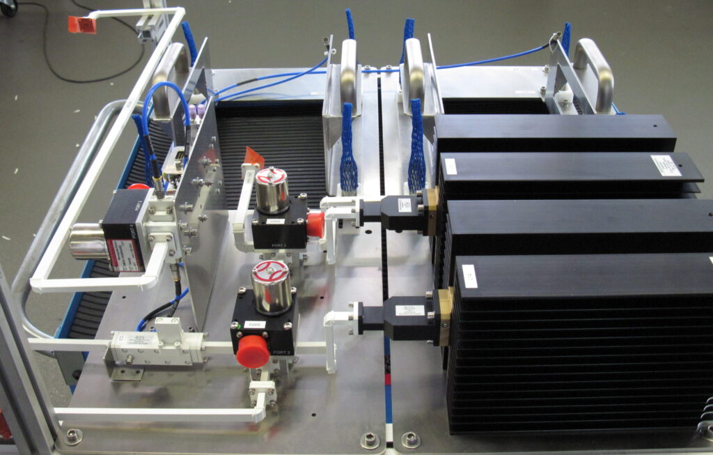
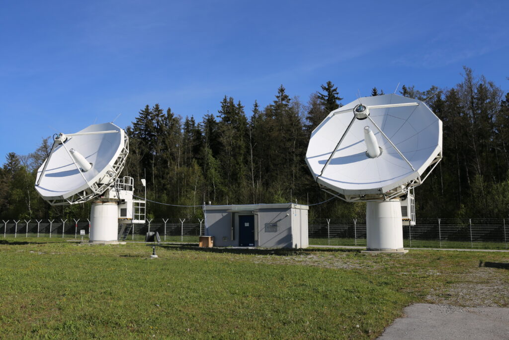
The figures illustrate the CAD models of all feed feed combiners, the final feed system and its integration in the feed tube, the switching unit for the BFLGS feed and the feeds installed in the antennas at DLR Weilheim*
Key technical challenges:
- Operational mode switching
- Highly integrated waveguide structures to minimize losses
- Compact multilayer waveguide design
- Thermal design and analysis for adequate power handling capability
- High isolation between Rx and Tx unit
Key functionalities:
- Ku- and Ka-band multimode operation with electronic switchable mode selection (between IOT to TC)
- TE21 mode monopulse tracking capability
(Rx-Trk: 25.50 – 26.56 GHz) for BFLGS, FLGS & DGS - Telecommand
(Tx TC: 27.5 – 27.6 GHz) for BFLGS, FLGS, DGS - Telemetry
(Rx TM: 19.6 – 19.8 GHz) for BFLGS and FLGS - In-Orbit Test
(Rx IOT: 23.185 – 23.225 GHz) for BFLGS - Data downlink
(Rx DL: 25.50 – 26.56 GHz, Rx DL IOT 25.50 – 26.01 GHz) for BFLGS, FLGS & DGS
*Credit: DLR, https://www.dlr.de/rb/desktopdefault.aspx/tabid-11840/